Counterbore holes are a useful feature for recessing fasteners and seals in CNC-machined components and mechanical assemblies. The heads of the fastener sit flush with the component’s surface for added strength, stability, and safety.
In this post, we’ll explore what a counterbore hole is, why and when to use them, and how to show them on an engineering drawing.
What is a counterbore hole?
A counterbore hole is a two-part feature: a larger-diameter, flat-bottomed recess (the counterbore) is machined coaxially above a smaller pilot hole. This design allows the head of the fastener, such as a bolt or a socket head cap, to sit flush with or below the surface, with the counterbore’s sidewalls perpendicular (90°) to the surface, and the bottom of the counterbore flat. These features distinguish it from conical countersinks.
Technical Characteristics
- Counterbore Diameter: Larger than the fastener head for clearance.
- Counterbore Depth: Deep enough to fully recess the fastener head.
- Pilot Hole: Matches the fastener’s shank or thread diameter.
- Symbol: ⌴ is used in engineering drawings.
Counterbore Holes vs. Other Holes
| Feature | Counterbore Hole | Countersink Hole | Through Hole | Blind Hole |
|---|---|---|---|---|
|
Geometry |
Cylindrical and Flat-Bottom |
Conical and Angled |
Passes Through the Part |
Partial Depth |
|
Purpose |
Recesses Cylindrical Head |
Seats Conical Head Flush |
Fastening/Clearance |
Locating/Partial |
|
Wall Angle |
90° |
82°/90° Conical |
N/A |
N/A |
|
Symbol |
⌴ |
⌵ |
None |
None |
Why and When to use Counterbore Holes in Product Design
When and why to use counterbore holes in flush mountings for function and aesthetics?
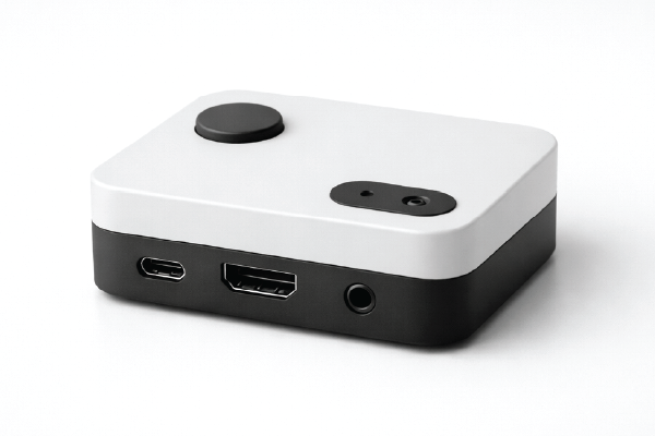
When the fastener head should not protrude above the surface for safety, aesthetic, or functional reasons, it prevents snagging, enables sliding and stacking, and creates a clean look—for example, in high-end furniture and consumer electronics.
When and why use counterbore holes in high-strength mechanical joints?
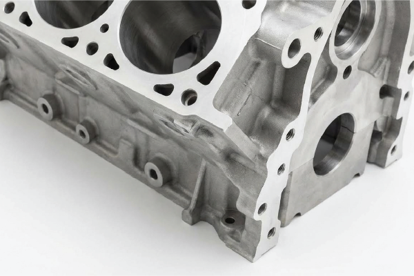
When large fasteners are needed to handle high loads or stresses, such as in machinery frames or automotive engine blocks, counterbores can accommodate strong fastener heads, ensuring secure, high-strength joints.
When and why use counterbore holes for precision and tolerance control?
When tight controls over fastener position, depth, and alignment are required, for example, in aerospace assemblies and precision equipment, counterbores ensure proper seating, alignment, and load distribution, which is critical for safety and performance.
When and why use counterbore holes with surface profile and sealing?
When the assembly surface must be smooth for sealing, sliding, or stacking, such as gasket joints or PCB mounting, it’s a good idea to recess fasteners to reduce snaking and mitigate injury risks.
When and why use counterbore holes for enhanced safety?
When protruding fastener heads could cause injury or interfere with moving parts, for example, in automotive interiors and children’s furniture. Recessed fasteners reduce snagging and injury risks.
When and why use counterbore holes when using certain fasteners?
When the assembly will use washers, bolts, gaskets, o-rings, socket head cap screws, fillister head screws, or specialty counterbore screws.
Real-World Applications and Examples
| Industry/Product | Example Use Case | Function of Counterbore Hole |
|---|---|---|
|
Engine Blocks and Suspension Systems |
Flush bolt heads for sealing, safety, and assembly efficiency. |
|
|
Aircraft Landing Gear and Engine Mounts |
Flush fastener mounting for reduced drag and structural integrity. |
|
|
Board Mounting and Device Internals |
Prevents interference, enables stacking, and clean internal structure. |
|
|
Structural Frames and Heavy-Duty Joints |
Accommodates large fasteners and ensures robust connections. |
|
|
Visible Fasteners and Sliding Components |
Sleek appearance, safety, and flush mounting. |
Design Guides and Best Practices
Technical Drawings and Visualization
- Counterbore Symbol: ⌴, with diameter and depth specified.
- Dimensional Example: Counterbore diameter x depth, for example, ⌴ 11 mm x 6.8 mm, is then followed by pilot hole size.
- Assembly Drawings: The counterbore appears as concentric circles in top view and as stepped holes in section view.
Dimensional Guidelines
- Counterbore Diameter: Fastener head diameter + 0.1–0.2 mm clearance.
- Counterbore Depth: Fastener head height + 0.5–1.0 mm.
- Tolerances: ±0.05 mm (standard), ±0.02 mm (precision).
- Surface Finish: Ra 3.2 μm (standard), Ra 1.6 μm (painted), Ra 0.8 μm (optical).
Material and Manufacturing Considerations
- Material Choice: Aluminum, stainless steel, and plastics.
- Machining: Prototek drills a pilot hole first, then uses a counterbore cutter or end mill to create the recess.
- Quality Control: Prototek uses calipers or CMMs for verification. Maintaining the concentricity and surface finish.
Common Mistakes to Avoid
- Over-specifying tolerances = cost increases
- Insufficient material thickness = risk of cracking
- Poor alignment between the pilot and the counterbore
- Unnecessary counterbores = increased cost and complexity.
A Summary of When to use Counterbore Holes
| Use Cases | Why use counterbores? |
|---|---|
|
Flush Mounting |
Safety, aesthetics, and functional surfaces. |
|
High-Strength Joints |
Accommodate large fasteners and robust connections. |
|
Precision Assemblies |
Tight tolerances, secure seeting, and alignment. |
|
Sealing or Smooth Surfaces |
Gaskets, seal supports, and leak prevention. |
|
Enhanced Product Appearance |
Hidden fastener heads and clean look. |
Complex Parts and Assemblies with Prototek
Prototek’s advanced digital manufacturing capabilities enable speedy, cost-effective production of complex parts and assemblies. We can streamline your product development process and accelerate the time-to-market.
Our range of services and solutions includes additive manufacturing, CNC machining, cast urethane, and sheet metal fabrication. They allow us to tackle even the most challenging design requirements with precision and efficiency.
Partnering with Prototek ensures access to cutting-edge technology, expert engineering support, and a commitment to delivering high-quality results that meet your exact specifications.
FAQs
Define: Counterbore Hole
A counterbore hole is a cylindrical recess that is machined into a workpiece to accommodate the head of a fastener, such as a bolt or screw. The counterbore provides a flat, recessed area for the fastener head to sit below the workpiece’s surface, allowing a flush or slightly recessed appearance.
How to dimension counterbore holes?
Counterbore holes are dimensioned by specifying the diameter and depth of the counterbore. The diameter and depth of the through hole should also be specified. The counterbore diameter should be larger than the fastener head, and the depth should be sufficient to accommodate the fastener head. The through-hole diameter and depth should be specified to ensure proper fit and function of the assembly.
How to counterbore a hole in metal or plastic?
To counterbore a hole in metal or plastic, follow these steps:
- Secure the workpiece in a stable position.
- Select the appropriate counterbore tool for the desired hole size.
- Align the counterbore tool with the existing hole.
- Carefully drill to the specified depth to ensure a clean, even surface.
How to make a counterbore hole in SolidWorks?
To create a counterbore hole in SolidWorks, follow these steps:
- Open your part file in SolidWorks.
- Select the face where you want to create the counterbore.
- Click on the “Hole Wizard” tool in the Features tab.
- In the Hole Wizard PropertyManager, select the “Counterbore” option.
- Specify the counterbore diameter and depth.
- Choose the appropriate hole type and any other required parameters.
- Click “OK” to create the counterbore hole.